The new MDE manifold and valves. Some initial thoughts from a divers perspective.
This is only the view of TFT and is not meant to take the place of an engineers report or an official review. Photographs taken by Gareth Lock.
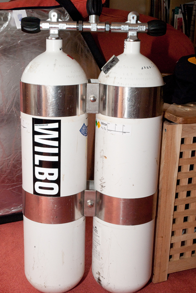
For reference a comparison was made against a set of Agir Brokk valves and manifold and Sherwood rubber handwheels fitted to a set of 12litre 232bar working pressure (WP) Eurocylinders with 192mm centres.
Prior to fitting:
At first glance, the MDE set looked to be well made and sturdy. Being made by MDE - Midland Diving Equipment we were expecting/hoping that this would be the case.
Straight away after unpacking - we noticed that they lack the smooth shiny finish of the older “facing o-ring” style MDE valve – something we hadn’t expected. The finish is now more of a burred mottled effect – more in line with some of the other manifolds available. We noted that the WP is stamped both on the valves and the manifold itself. We were supplied with 232bar WP valves and a manifold rated to 300bar WP. The MDE valves are M25 valves – so adhere to the current regulations on the inlet valve gauge for gas fills, not the proposed EU ones.
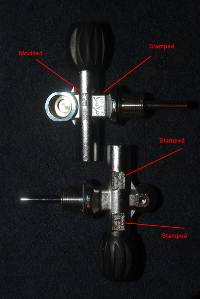 Markings on the valves and manifold are either formed into the mould during the casting process or stamped in after the casting process. The valves – other than the WP appear to have a manufactured date, a batch number and the EN250 stamp on one side and MDE’s logo (and WP) on the other. Everything except the “232 bar” on the valves is stamped.
We did note that what appeared to be ‘contact points’ (indicated by lines in image below) during the moulding process still appear on the outside of the valves, left proud of the surface slightly. I thought this looks a little untidy and could have been finished off prior to launch.
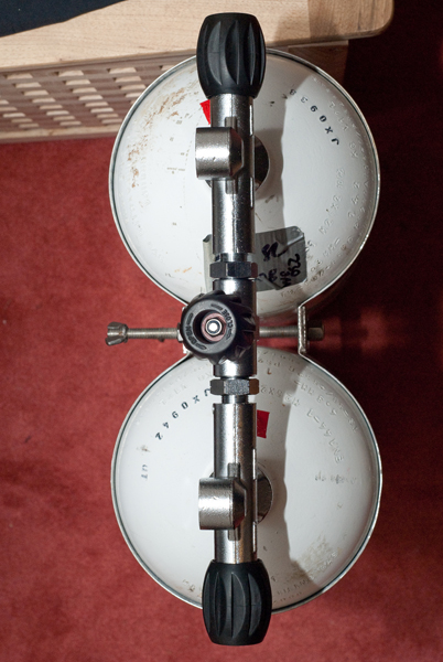
 The manifold isolator valve has now been moved into the centre of the manifold – enabling shutdowns with either hand now – as opposed to the previous MDE manifold where the isolator vale was biased towards one side (from all of the images I have seen – the right hand post when wearing the set).
One of the first surprises we found was the way the handwheel for each valve has been connected to the valve spindle. For some reason MDE have chosen to use a Nyloc nut in place of the more ‘traditional’ slotted nut with its ‘locking pin’ in the top – not sure why they diverted away from this type of securing nut – as their old valves used them. This of course now means that to gain access to the valve body a socket (10mm) is now required – and potentially in your dive tool kit too if you are away on a trip. The handwheels are also a little smaller than the Sherwood version fitted to the Agir Brokk hardware. In water time will tell if this will be an annoyance or not.
I am awaiting confirmation on what the o-rings are made from – but Viton is the candidate here – as the spec says that they are O2 adiabatic compression compatible.
We did weigh them – and compared to the Agir Brokk hardware – there was little difference – so there should be no issues with having to move weight around the twinset to balance it.
Stripping a valve down:
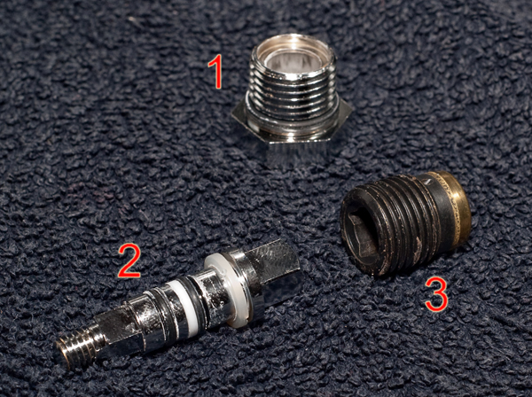
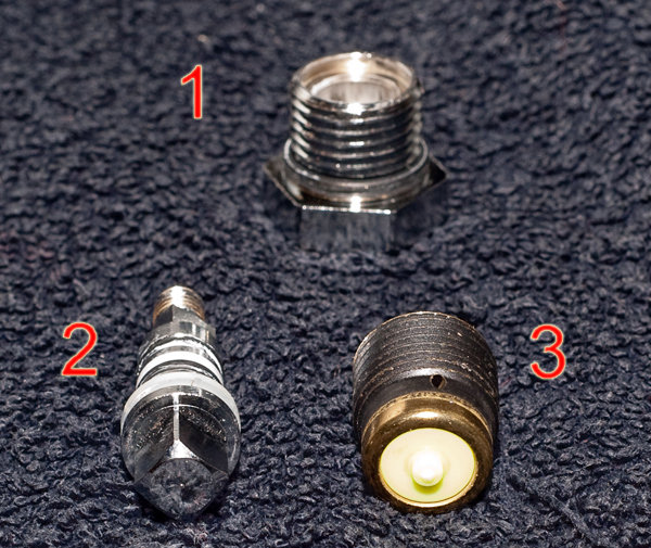
After finding a 10mm socket and taking the Nyloc nut off, the handwheel can be removed leaving the valve spindle in place. Referring to image below: Loosen the locking nut (1) and remove. The spindle section can now be removed. This leaves the plug (3) in place. This can be removed using the spindle section to unscrew the plug.
You will see from the images below that the valve plug (3) has a hole in it. We assume this is something to do with the pressure equalisation across the valve plug – and should make shutting the valve down easier.
Assembling the valves and manifold into the twinset:
It would appear that the manifold is ‘sided’ – i.e. one valve fits one side of the manifold only. Therefore you cannot help but put it together the correct way around.
After prepping the o-rings with Crystolube, it was time to screw the first valve into the cylinder.
Now I should say here that like most twinset owners I know where all the stickers are on the set – and in my case they are all placed where I want them. The ID stickers that we use on them is always outer-most on the set and any required stickers are placed where they are visible to a fill station – but not on the outside of the set (as I like a clean twinset.. )
So the first valve is screwed in, hand tightened and then nipped up by 1/16th. I then look down and find that all the stickers are no longer in the correct place. Sure enough – screwing the other valve in gives the same results except a mirror image. One ID sticker is now on the back of the set and the other on the inside behind the backplate.
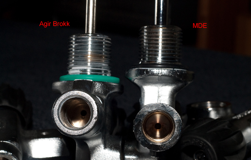
So after much head scratching Gareth and I count the threads on the valve. And recount them. Sure enough the MDE valve has 1 less thread – plus a bit – hence why the stickers are not in the same place here.
The valves were inserted and tightened up by the same amount. The manifold was screwed in and the centres were measured for the bands at 192mm. Bands were applied and tighten up. Anyone moving from an Agir Brokk or similar valve system will notice the same issues. New stickers for your cylinders will be needed if you are bothered about their placement..
At this point we also noticed that the retest mark on the cylinders was different between the two cylinders (the red squares shown). Before the set was disassembled, we noted the red squares both on the front of each cylinder. As the retest marks are stamped manually – we can allow a little for human sight – but it appears there is more than this.
This might indicate that the threads are slightly different in length – but as we didn’t have any technical way of deducing the length. Depending on which side of the valve we were counting – we counted either 9 or 10 threads for the MDE and either 10 or 11 for the Agir Brokk.
Shutting the valves down:
We did a comparison between the two types of valves – and this is what we found.
MDE valve – from fully open to fully closed: 2 turns. [1]
MDE isolator – from fully open to fully closed: 1.5 turns.
Agir Brokk valve – from fully open to fully closed: 3.25 turns
Agir Brokk isolator – from fully open to fully closed: 2.5 turns
[1] Just. Though most people would never do the full 2 turns – as they don’t want a cylinder wrenched fully open or closed – as this can be problematic underwater if the valve seizes.
That’s it for this part of the review. There will be another review once we’ve been in the water with them initially and also a review to cover the 3 months we’ve had them.
I would also add the shots comparing the layouts of the valves side by side so that people can see the difference in lengths (valve longer). Also show the plug inside the valve so that people can see the ‘square’ hole. In fact, I would upload most of the photos so that people can see what they look like and the whole shabby make-up
Larger Images:
We've made all of the images that Gareth took available - not just the ones seen above..
Large images are now available: Images of Life Photography - MDE Gallery
If you want a full-size image to download just click on the download button, if you want a more detailed view, move the mouse over the image and a magnified view will be available
Credits:
The MDE manifold and valves were very kindly lent to us for a few months by Antony from ScubaDivingStore (Scubadivingstore.co.uk) based down in Torquay. What a nice chap and very approachable.

